Summary
- IMM is Intact’s patent-pending automated meshfree FEA technology
- IMM can be used to simulate and optimize any geometry/material representation (e.g., B-reps, STL/PLY, voxels, implicit, g-code)
- IMM is just as accurate as any other conventional mesh-based FEA tool
What is Immersed Method of Moments™ (IMM)?
Immersed Method of Moments (IMM) is a technology that uses the Finite Element Analysis (FEA) for performing simulation tasks, without the need to build a conformal mesh. IMM adopts an immersed-grid methodology where the geometry is “immersed” in a non-conformal background grid; and our patent-pending moment-vector technology is used to compute geometry and material dependent quantities (e.g., element quadrature) at runtime for the FEA.
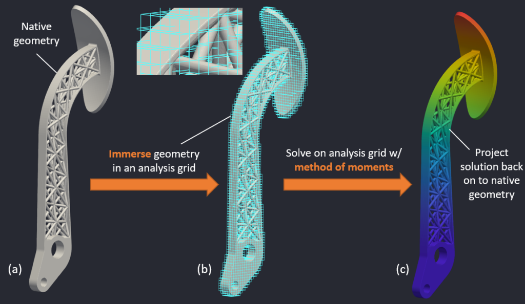
The above picture (Figure 1) captures the essence of IMM. The geometry (shown in Figure 1a) is immersed in a background analysis grid (Figure 1b). The elements in the analysis grid are conventional FEA elements (e.g., 8-noded hexahedral linear elements or 27-noded hexahedral quadratic elements), except that the quadrature used for the elements are computed using the method of moments. For instance, an element that is completely inside the the geometry will have quadrature that is different from an element that is only partially inside the geometry. After computing the solution on the analysis grid, the quantities of interest are projected back on to the native geometry (as shown in Figure 1c).
Why is IMM a big deal?
IMM is a geometry-agnostic FEA methodology that eliminates meshing-related bottlenecks that break conventional FEA-based workflows, especially in generative and additive manufacturing applications. The part geometry can be in any format: surface meshes (STL/PLY), boundary representations (B-reps), implicits, voxels, g-code, or even CT scan data. This means that the same IMM workflow can be used for simulating the performance across all stages of the part lifecycle —from initial geometry setup (CAD formats) to light-weighting and optimization (surface meshes or implicits) to as-planned design (g-code) to as-manufactured design (CT scan data).
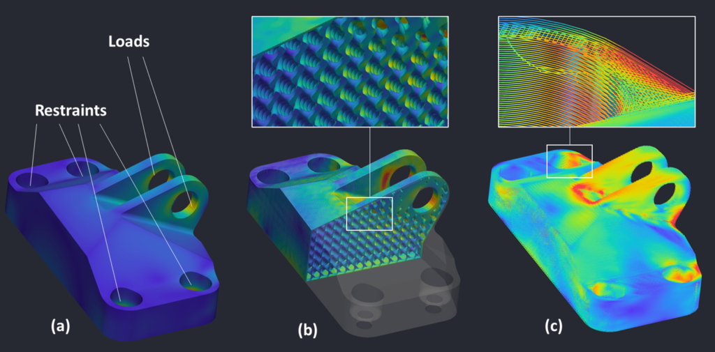
The above picture (Figure 2) shows the simulation results (Von Mises stress) of three geometric representations: Figure 2a shows corresponds to a B-rep CAD geometry, with the loads and restraints applied at corresponding surfaces. Figure 2b corresponds to that of a generatively-designed part, with spatially varying gyroid infill. Figure 2b shows that IMM is able to capture the complicated distribution of stress fields at the lattice infills. Figure 2c corresponds to that of a g-code representation of the part, which shows that IMM is able to capture the stress distribution even at the g-code path level.
How accurate is IMM?
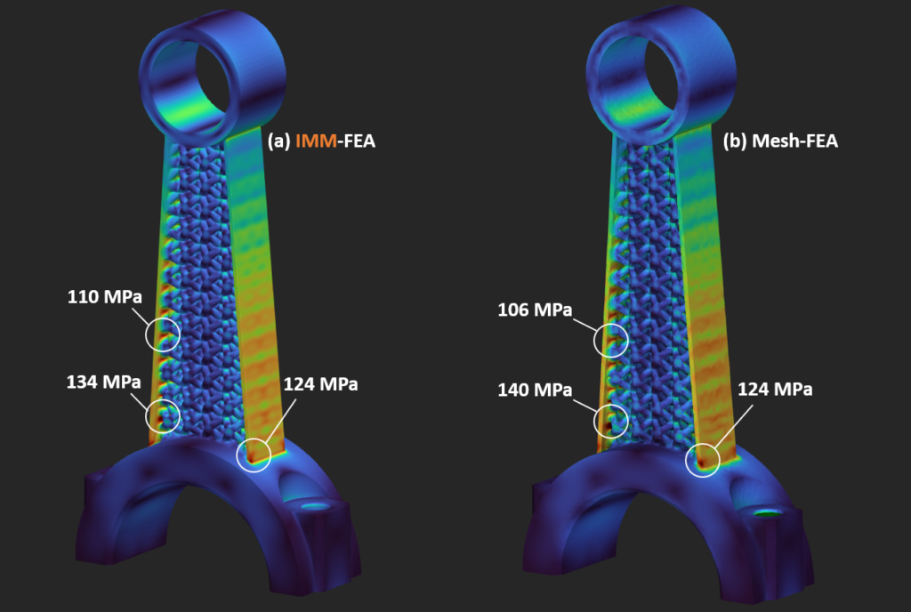
The picture below shows a validation study performed, where IMM-FEA is compared against a conventional mesh-FEA. The geometry creation and the mesh-FEA simulation is performed in nTopology. The Von Mises stress distribution for both IMM-FEA (Figure 3a) and mesh-FEA (Figure 3b) are shown, which shows a very decent agreement between mesh-FEA and IMM-FEA, even at sharp corners and intersections between the lattice structures and the outer wall. This confirms that IMM-FEA is just as accurate as conventional mesh-FEA methods.