
Overview
- Continuous fiber reinforcement allows for increased mechanical performance while being lightweight. For many designs, adding composite reinforcement locally can extract most of the performance, but there are currently no good tools to easily tailor and optimize composite placement.
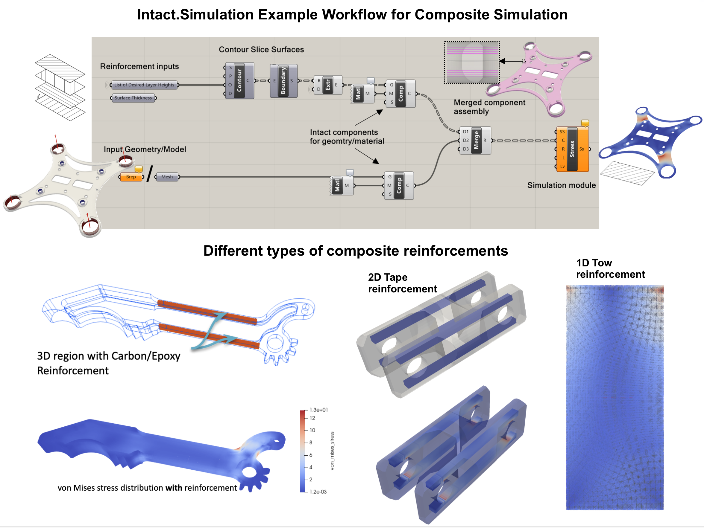
- Intact.Simulation can effortlessly analyze various composite reinforcement strategies to optimize part performance. The reinforcement geometry can come in various formats (e.g. 3D regions as B-reps, composite plies as 2D surfaces, and tows as 1D line segments) to help make efficient and impactful design decisions without any format change.
- Intact.Simulation can also be used to tailor fiber placement for Continuous Fiber 3D Printing Processes by allowing users to quickly study the effect of reinforcing walls, infills, and other additive process parameters and features
Continuous Fiber Reinforcement Design and Validation using Intact.Simulation
Continuous fiber (CF) reinforcement in composites comes in many forms such as plies, tapes, and tows. Often 3D representation is not suitable, and 2D (plies and tapes) and 1D (tows, G-code) representations are needed to efficiently model the reinforcement. In addition, now there are advanced manufacturing techniques including Additive Manufacturing and Automated Fiber Placement that can tailor the placement of these reinforcements in 3D components.
To place the reinforcements optimally, a simulation-based design and validation workflow is a must. However, traditional mesh-based FEA tools don’t work effectively and often break the design iteration workflow because of bottlenecks such as meshing and representation conversion, that are time-consuming and/or require considerable manual effort. In addition, spatially varying and anisotropic materials create even more challenges for mesh-based FEA.

Intact.Simulation for Rhino Grasshopper makes quick design iterations as well as accurate validation of CF composites possible
Predicting the impact of CF reinforcements is incredibly simple using Intact.Simulation. Intact allows the simulation of multiple geometry and material types within the same system via its Immersed Method of Moments (IMM) technology. Put simply, we can model reinforcement plies as 2D surfaces and tows as 1D curves embedded within the 3D model of a part. With defeaturing, representation conversion, and meshing out of the loop, design iterations are rapid and effortless. When ready for validation, a high-fidelity model for the composite part can also be simulated by the same workflow without any additional preprocessing.
If you can model it, Intact.Simulation can simulate it!
Example Design Study: Increase the Stiffness of a Drone Frame by Adding Composite Plies
Drones are required to be lightweight and stiff, making reinforcement with composite plies a great solution. We investigate the use of Continuous Carbon Fiber with Nylon 6 ^1 as the base material for fabricating a drone frame, as shown in Figure 1.
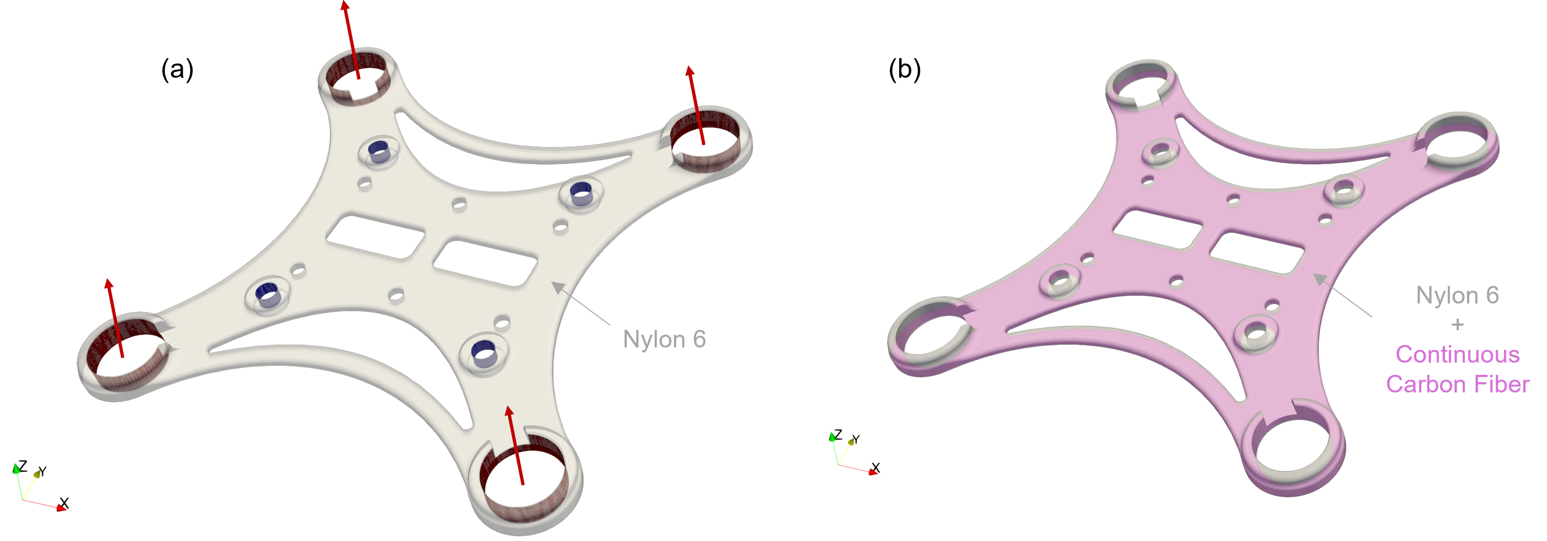
Figure 1: Drone frame loading scenario (a) with blue fixed constraints and red vector loads in the +Z direction representing the thrust. Drone reinforcement ply surface is shown (b).
Based on average drone accelerations and masses, a thrust force for each rotor was calculated. These thrusts from non-adjacent rotors create a net bending moment in the frame portion of the drone, Figure 1. The deformation of the upper drone frame for the described loading scenario consisting of only base material is shown in an animation alongside a reinforced frame, Figure 2.
Figure 2: Deformation animation of the base material drone frame (a) and the drone frame with reinforcement (b)
A large amount of deformation occurs from the acceleration of the drone, indicating that the frame is not stiff enough with only base material. After adding reinforcement, the deformation is seen to drastically decrease, Figure 2b.
Where do we put reinforcements?
Now that it is clear the drone frame is not stiff enough with just the base material, the next step is to find a reinforcement layout that meets stiffness requirements. For a relatively simple case like this, it is clear the drone needs higher resistance to bending. Therefore, it would make the most sense to apply reinforced fiber plies above and below the frame’s neutral axis2, Figure 3a.
However, the big question left unanswered is just how many plies are sufficient and in what layup, Fig 3 (b)-(c)? To solve this, simulations can provide quick insight by analyzing many different combinations of layups which help reduce the time and labor-intensive process of printing and testing. Currently, though, traditional FEA is not set up for seamless simulation of 3D geometries with arbitrary localized reinforcements, which can come in different shapes and formats.
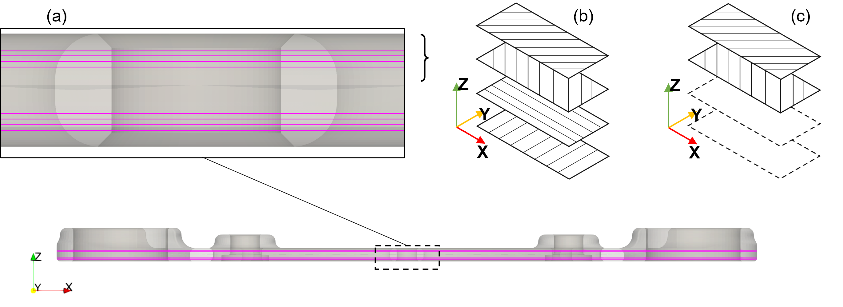
Figure 3: Vertical location of reinforcement ply surfaces extracted via CAD software (a) with corresponding symmetric layups about the neutral axis: [45,-45,0,90] (b) and [45,-45] (c).
The process of placing reinforcement may also be automated using Intact.Generative based on simulation of the frame without reinforcements
Intact.Simulation to the rescue:
Intact’s Immersed Method of Moments (IMM) technology allows the simulation of the 3D drone frame with embedded 2D composite plies (Figure 4a) without any format conversion or meshing issues. These ply surfaces can be submersed within the 3D frame geometry due to the solver’s independence from conformal meshes used in traditional FEA. The design study can easily be set up within an automated workflow, for example, using Rhino Grasshopper (Figure 4b).
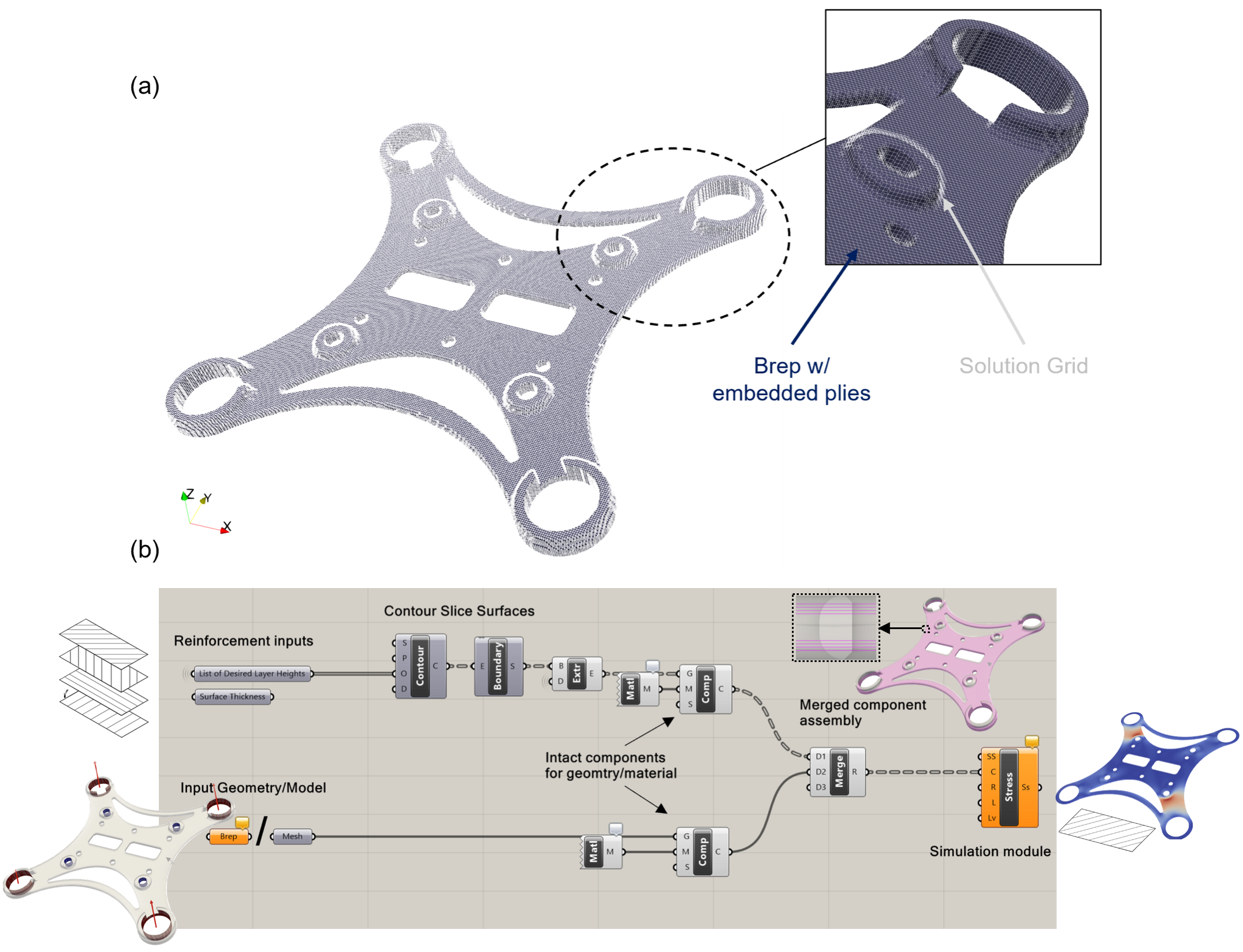
Figure 4: Immersed method of moments (IMM) grid for the immersed frame and ply geometries (a) along with an example of the grasshopper plug-in workflow used.
Results: Effect of Composite Reinforcement
Once the loading scenario is made and the location(s) of reinforcement are decided, Intact can quickly simulate the displacements, Figure 5, and stresses/strains of the system.
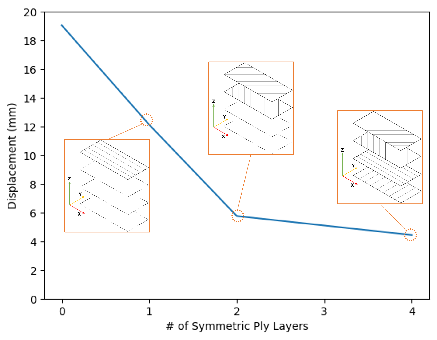
Figure 5: Plot of displacement in mm versus the # of symmetric ply layers.
In the case of this drone frame, it is clear from Figure 5 that adding layers of reinforcement can drastically decrease the maximum displacement of the system, or drastically increase its stiffness. Specifically, adding just two (symmetric) layers of reinforcement increases the stiffness by nearly 70%.
Stress in the Plies
Looking into stress distributions, a large bending stress is present at each spar of the drone frame before reinforcement. The magnitudes of this bending stress decrease considerably with increasing reinforcement (by over 50%).
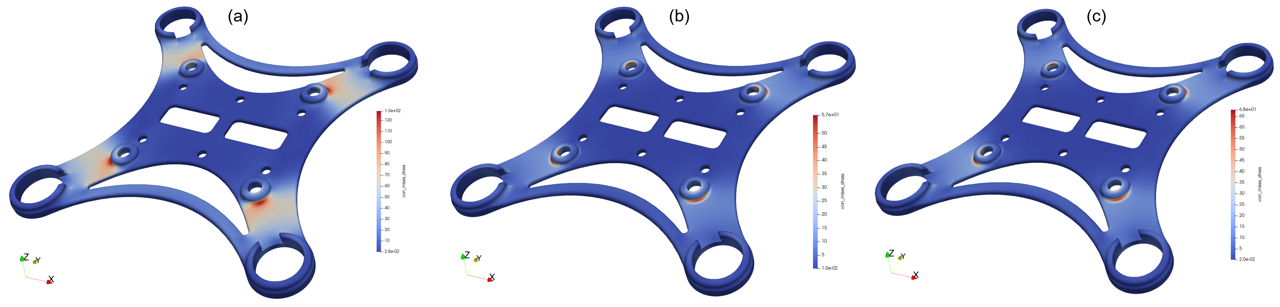
Figure 6: Stress distribution of the drone frame under acceleration loading with only nylon 6 (a), [45,-45]s plies (b) and [45,-45,0,90]s plies (c)
Furthermore, since Intact.Simulation is not doing any model simplification using reduced order models, we can easily obtain stress and other results for the composite plies. Figure 7 compares stress in the different plies.
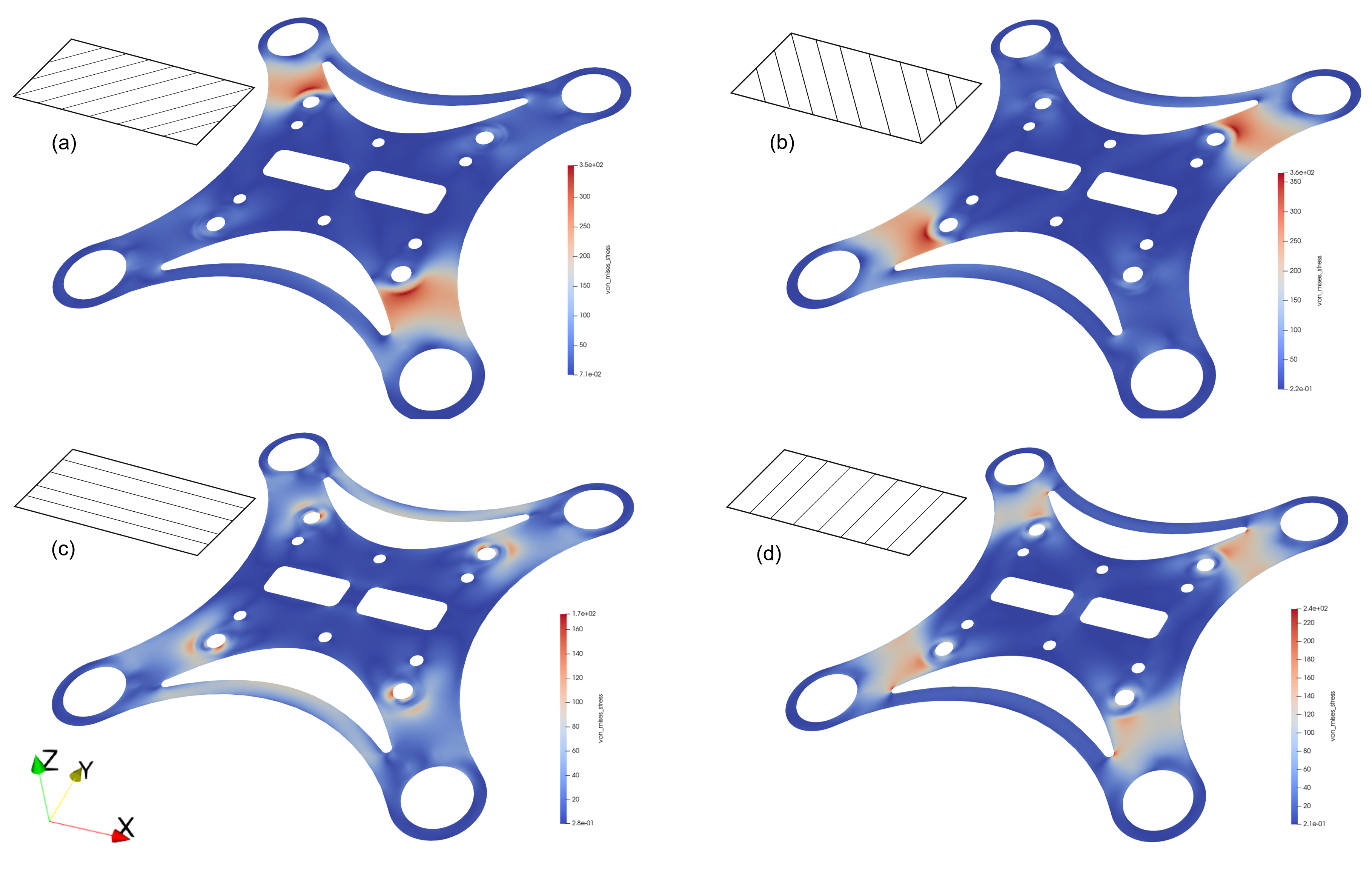
Figure 7: Stress distribution of the reinforcement plies under acceleration loading with the top layer (a), the second layer (b), the third layer (c), and the layer closest to the neutral axis (d).
By looking at the stress distributions of the individual ply surfaces, the directional properties of the composite plies are immediately visible. Notably, in the +/- 45-degree layers the spars with bending forces orthogonal to the fiber direction are far higher. Also, there is a difference in the 0/90 degree ply stress distributions as the direction of the smaller connecting material between the upper/lower spars is aligned directly with the 0-degree oriented fibers. Lastly, the magnitude of stress is far higher than that of the unreinforced frame showing that these plies are helping carry much of the load/stress.
Footnote
- Chosen for demonstration purposes
- We assume a composite FDM manufacturing process that requires some layers of base material above/below the top/bottom-most layers of reinforcement respectively.